|
 The Ketema Schutte and Koerting Type 340 Simplex Continuous Pipeline Steam Jet Heater
is a simple, yet efficient device for low-cost, in-line heating
of process liquids by direct steam injection. Designed for direct
connection to liquid and steam lines, the heater mixes cold
liquid and steam and raises the temperature of the liquid instantly
to predetermined levels. When heater is in operation, there is
no water pressure drop thru the unit. The Ketema Schutte and Koerting Type 340 Simplex Continuous Pipeline Steam Jet Heater
is a simple, yet efficient device for low-cost, in-line heating
of process liquids by direct steam injection. Designed for direct
connection to liquid and steam lines, the heater mixes cold
liquid and steam and raises the temperature of the liquid instantly
to predetermined levels. When heater is in operation, there is
no water pressure drop thru the unit.
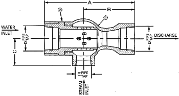
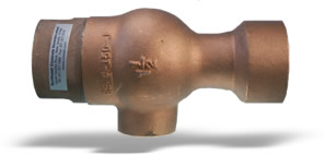
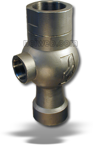
The Ketema Schutte and Koerting Type 340 Simplex Heater consists of a onepiece body and diffuser and a removable combining tube. The straight through design of the unit permits handling slurries and liquids with suspended solids and semi-solids as well as clear liquids. The heater can be turned on and off with a minimum of vibration.
These heaters are normally made and stocked in bronze and stainless steel, but can be supplied in other machinable and castable alloys. There are no moving parts to get out of order, adjust, or repair.
OPERATION
Liquid under pressure enters the heater and flows through the in-line combining tube. Steam enters the heater through the steam connection and passes through the combining tube orifices. Intimate mixing of steam and water occurs in the tube and venturi. Thus, the steam is completely condensed and the liquid is heated before it is discharged into the connecting pipeline.
These units can eliminate resistance or bayonet heaters and containment vessels. The straight through in-line design minimizes clogging. The Ketema Schutte and Koerting Fig. 340 heaters have a low initial cost, no moving parts, are easy to install and require little or no maintenance.
The Ketema Schutte and Koerting Type 340 Heater, available in three sizes, operates with maximum steam pressure of 180 psig, and a water rate from 15 to 400 gpm. Maximum inlet water temperature is 150 °F, and maximum temperature rise is also 150°F. Steam pressure should be at least 5 psi greater than inlet water pressure.
Shown above is a nomograph for determining the capacity, steam pressure, and steam consumption of a 2" heater. The table of capacity factors, Capacities Table, simplifies size selection for other flow rates.
For inlet water temperatures exceeding 70°F, requirements decrease approximately 2% for each 20°F (up to 150 ° F); increase 2% for each 20°F under 70°F inlet water temperature.
The following example explains the use of Curve H: What heater size, steam pressure and rate are required to heat 320 gpm of water at 60 psig from 70° F to 100° F ?
Since discharge capacity (flow rate, gpm) is off curve, refer to Table 10 and divide 320 by 2.3 capacity factor. Locate 139 gpm on discharge capacity scale and project vertically up to the intersection with the 30 °F temperature rise line. From this point, project horizontally across to 60 psig inlet water pressure curve and vertically down to steam pressure of 75 psig. Return to horizontal projection and across to steam rate of 1,750 pph. Final answer is 2.3 times this figure, or 4,025 pph of steam at 75 psig using a 3" heater size.
|