Type 540 Pipeline Steam Heater |
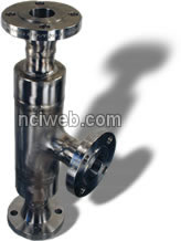 Type 540 Pipeline Steam Heaters are used in a wide variety of liquid heating applications. Heating takes place directly in the pipeline. Liquid heating capacities range from 4 gpm to over 1600 gpm. When in operation, there is a negligible liquid side pressure drop through the heater. The straight through in-line design of the Type 540 Pipeline Heater accommodates slurries as well as clean liquids. Type 540 Pipeline Steam Heaters are used in a wide variety of liquid heating applications. Heating takes place directly in the pipeline. Liquid heating capacities range from 4 gpm to over 1600 gpm. When in operation, there is a negligible liquid side pressure drop through the heater. The straight through in-line design of the Type 540 Pipeline Heater accommodates slurries as well as clean liquids.
Some typical applications include hot water supply stations, preheating of tank washdown liquid, plant or shipboard heating, in-line cooking, and slurry heating.
Operation: Steam under pressure enters the heater and is injected
through a perforated combining tube directly into the aqueous
liquid stream to be heated. Vigorous mixing of the steam and
liquid takes place in the combining tube where the steam is
condensed and heated liquid is discharged from the heater.
For proper operation, the steam pressure should be at least
15 psi greater than the liquid inlet pressure. |
| |
| CONSTRUCTION |
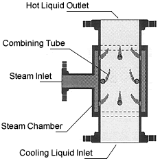 The Type 540 Pipeline Heater consists of a steam chamber and a combining tube. The heater is available in almost any material including carbon steel, stainless steel, Monel, Hastelloy, and titanium. Connections are typically ANSI flanged, but the unit can be supplied with threaded, butt weld, or sanitary connections as required. See page 9 of this bulletin for the Type 540S Sanitary Pipeline Heater. The Type 540 Pipeline Heater consists of a steam chamber and a combining tube. The heater is available in almost any material including carbon steel, stainless steel, Monel, Hastelloy, and titanium. Connections are typically ANSI flanged, but the unit can be supplied with threaded, butt weld, or sanitary connections as required. See page 9 of this bulletin for the Type 540S Sanitary Pipeline Heater.
- HOT LIQUID OUTLET - Hot liquid is discharged with a negligible liquid side pressure loss.
- COMBINING TUBE - Steam is distributed evenly into the process flow for complete condensation of the steam and heating of the liquid.
- STEAM INLET - Steam under a pressure greater than the liquid pressure enters the heater.
- STEAM CHAMBER - A jacket around the combining tube is designed to evenly feed steam to the combining tube.
- COOL LIQUID INLET - Liquid to be heated enters the heater.
|
| |
| INSTALLATION / MAINTENANCE: |
 The Type 540 Pipeline Heater may be installed in any horizontal or upward flowing vertical position in relation to the liquid flow direction. Isolation valves and pressure gauges are recommended on the steam and liquid inlet lines. The steam isolation valve must be located so that any liquid or steam line condensate drains toward the heater. A minimum straight length of five inlet pipe diameters upstream of the heater is required for liquid flow straightening. A temperature gauge is recommended in the discharge line for visual indication. At the outlet a minimum of eight pipe diameters is recommended before the point of use. There are no moving parts, and therefore no routine maintenance is required. Occasional cleaning of the combining tube may be required if the application involves slurries or cooking stuffs. The Type 540 Pipeline Heater may be installed in any horizontal or upward flowing vertical position in relation to the liquid flow direction. Isolation valves and pressure gauges are recommended on the steam and liquid inlet lines. The steam isolation valve must be located so that any liquid or steam line condensate drains toward the heater. A minimum straight length of five inlet pipe diameters upstream of the heater is required for liquid flow straightening. A temperature gauge is recommended in the discharge line for visual indication. At the outlet a minimum of eight pipe diameters is recommended before the point of use. There are no moving parts, and therefore no routine maintenance is required. Occasional cleaning of the combining tube may be required if the application involves slurries or cooking stuffs.
Performance Limits:
- The liquid temperature rise is limited to a maximum of 150° F.
- The inlet liquid temperature is limited to a maximum of 150° F.
- The steam pressure should be a minimum of 15 psi greater
than the liquid inlet pressure. It the pressure difference
is less than 15 psi, consult the factory.
- The liquid outlet temperature for water is limited by the
pipeline pressure as follows:
|
| |
| PIPELINE WATER PRESSURE, PSIG |
MAX. WATER OUTLET TEMPERATURE, F |
| 20 |
240 |
| 50 |
250 |
| 100 |
260 |
|
| |
| DATA REQUIRED FOR SIZING |
- Ps = Steam Pressure, psig
- Ws = Steam Flow, #/hr
- Pw = Water Pressure, psig
- ΔT = Temperature Rise, ° F
- ΔP = Ps - Pw, psi
|
| |
| LIMITATIONS: |
| 1. The final water temperature must
be a minimum of 20° F below saturation at Pw. |
| 2. ΔP must be a minimum of 15 psi, or consult the factory. |
| |
| SIZING EQUATIONS: |
| 1. Ws = 0.46(Qs)(AT). |
| 2. If Ps > 1.8 Pw, then M = (Ps + 13) / Ws. |
3. If Ps < 1.8 Pw, then M = - V(386 AP)(Pw + 15) / Ws. |
| |
| HEATER
SIZE |
M |
FLOW
RANGE |
1/2" |
.449 |
1-8
gpm |
| 3/4" |
.253 |
6-16
gpm |
| 1" |
.1554 |
10-26
gpm |
| 1-1/4" |
.0900 |
18-40
gpm |
| 1-1/2" |
.0662 |
26-60
gpm |
| 2" |
.0404 |
40-100
gpm |
| 2-1/2" |
.0283 |
60-140
gpm |
| 3" |
.0184 |
90-200
gpm |
| 4" |
.0101 |
160-400
gpm |
| 6" |
00449 |
360-900
gpm |
| 8" |
.002525 |
640-1600
gpm |
|
| |
| Sizing Example - Problem: |
| A pipeline heater is required to
heat 50 gpm of 35 psig pressure water from 80° F to 150° F.
There are two steam pressure sources available, 60 psig and 100
psig steam. |
| |
| Solution: |
| Step 1 Calculate
the required steam flow using Sizing Equation #1. Ws = 0.46(Qs)(
ΔT) = 0.46 (50 gpm)(70° F) = 1610 #/hr. |
| Step 2 Determine which equation to use for calculating M. 1.8(Pw) = (1.8)(35) = 63 psig. |
| Use Sizing Equation #3 if 60 psig pressure steam is to be used, or use Sizing Equation #2 if 100 psig steam is to be used. |
| For 60 psig steam, M = (386 x 25)(35 + 15) / 1610 = 0.431. |
| |
| A calculated value of M = 0.431 corresponds to a 1/2" heater in Table 1. Checking flow ranges, a flow of 50 gpm would be too high for a 1/2" |
| |
| Try 100 psig pressure steam using Sizing Equation #2 since 100 psig is greater than 63 psig. M = (100 + 13) / 1610 = 0.0702. |
| |
| From Sizing Table 1, choose the heater size with the next lowest M value. For a 1-1/2" unit, M =.0662 and 50 gpm is within the acceptable flow range. |
| |
| Use a 1-1/2" Type 540 Pipeline
Heater to heat 50 gpm of water from 80° F to 150° F, using
1610 #/hr of 100 psig pressure steam. |
| |
| Note: |
1 Pipeline sizes may need to be larger than the unit size to prevent excessive pipe pressure losses. |
| 2. Consult the factory when the required water rates fall outside the flow range of the calculated heater. |
| |
| Dimensional Information: |
 |
| Dimensions
in Inches |
| |
Nominal |
|
|
|
|
| Size A |
Capcity (GPM) |
Steam Inlet B |
C |
D* |
Wt. Lbs. |
| 1/2 |
4 |
1/2 |
3-3/8 |
10 |
7 |
| 3/4 |
10 |
1/2 |
4-1/8 |
10 |
8 |
| 1 |
20 |
3/4 |
4-5/16 |
11 |
9 |
| 1-1/4 |
30 |
1 |
4-3/4 |
11 |
12 |
| 1-1/2 |
50 |
1 |
5-3/16 |
12 |
17 |
| 2 |
80 |
1-1/2 |
6-3/16 |
13 |
25 |
| 2-1/2 |
120 |
2 |
6-1/4 |
14 |
28 |
| 3 |
175 |
2 |
6-5/8 |
14 |
45 |
| 4 |
300 |
3 |
8-3/8 |
16 |
70 |
| 6 |
700 |
4 |
10 |
18 |
115 |
| 8 |
1100 |
6 |
13-1/2 |
20 |
180 |
|
|
| * Dimension D varies with the application. The
dimension in the table is a typical overall length. |
| |
| Previous Page |