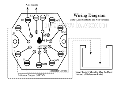
 Direct Mode: Single Level Service: With power applied to the control and the probe on terminal 3 out of the liquid, the load contacts are in their shelf position and a negative 12 VDC signal is present on terminal 4. (LED will not be lit) When the liquid rises to the electrode on terminal 3, the control energizes, changing the state of the load contacts and providing a plus 12VDC signal on terminal 4. (LED will be lit)
Inverse Mode: Single Level Service: With power is applied, with the probe on terminal 3 out of the liquid, the control energizes, changing the state of the load contacts and providing a negative 12VDC signal on terminal 4. (LED will be lit) When the liquid rises to the electrode on terminal 3, the control de-energizes, returning the load contacts to their shelf position and a plus 12VDC signal on terminal 4.
 SENSITIVITIES VS MAXIMUM PROBE WIRE DISTANCE
 MODEL NUMBER INFORMATION
 WIRING DIAGRAM
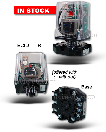
 Control Design: Solid state components enclosed in a clear Lexan plug-in style housing. Housing carries no NEMA rating.
 Direct Mode: Single Level Service: With power applied to the control and the probe on terminal 3 out of the liquid, the load contacts are in their shelf position and a negative 12 VDC signal is present on terminal 4. (LED will not be lit) When the liquid rises to the electrode on terminal 3, the control energizes, changing the state of the load contacts and providing a plus 12VDC signal on terminal 4. (LED will be lit)