RCM Flow Meter Specifications |
||||||||||||||||||||||||
|
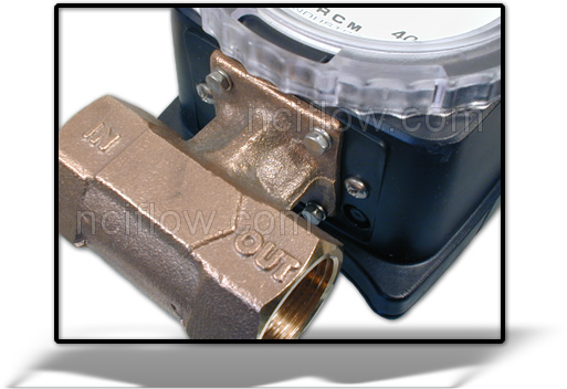
This meter was developed for industrial flow metering applications in which durability and reliability are important considerations. Accuracy, small size, low cost, minimal maintenance and resistance to accidental damage are the prime goals in the RCM design. Typical applications include: lube oil and cooling water monitoring, blending processes, reverse osmosis systems, and compressed air measurement. The RCM is available with a 420 mA output for interfacing with remote displays and controllers. Limit switches are available to provide high and low limit signals. A 01000 Hz frequency output is available to drive frequency based controllers and counters.
|
||||||||||||||||||||||||
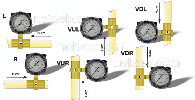
| Flow Direction Choices: | ||||||||||||||||||||||||
 |
||||||||||||||||||||||||
| Example of Model: | ||||||||||||||||||||||||
 |
||||||||||||||||||||||||
| Selecting Your Flo-Gage Model: | ||||||||||||||||||||||||
| A). Body Size - pipe at the meter inlet. Select from standard flow rates and body sizes. | ||||||||||||||||||||||||
| B). Series (Mounting Method) - 7 = threaded units provided with FNPT connections standard. 8 = wafer units mount between any standard 150 or 300 class flanges (or international equivalent). | ||||||||||||||||||||||||
| C). Material - 1 = Bronze | 2 = Monel | 3 = Stainless Steel (316) | ||||||||||||||||||||||||
| D). Flow Direction - Select L, R, VUL, VUR, VDL, VDR (see diagram below). | ||||||||||||||||||||||||
| E). Flow Rate (full scale) - Select from Standard Flow Rates and Body Sizes. | ||||||||||||||||||||||||
| F). Options - (if required) - Select from table of Options. | ||||||||||||||||||||||||
| G). Switches (if required) - 1S2 = One single pole double throw switch or 2S2 = Two single pole double throw switches. | ||||||||||||||||||||||||
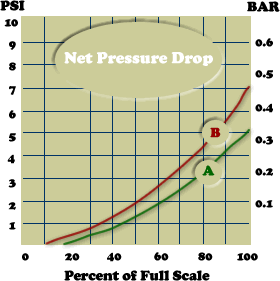
| Pressure Drop Characteristics: | ||||||||||||||||||||||||
|
||||||||||||||||||||||||
| Product Support Files / Links | ||||||||||||||||||||||||
| Flow Meter Cut-a-way | ||||||||||||||||||||||||
| View & Download Product Bulletins - Brochures | ||||||||||||||||||||||||
| Previous Page | ||||||||||||||||||||||||

 The RCM
is a differential pressure direct reading flow meter.