Flotect SERIES V6 Flow Switches |

|
| Monitor Flow in 1/2" to 2" Pipe, Explosion-Proof - Leak Proof Body
|
| |
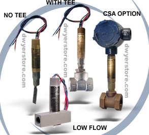
| Available in both a standard flow & a field adjustable low-flow design. Surprisingly
compact, the Flotect V6 Flow Switch is engineered specifically to monitor liquid, gas or air flows
in pipelines from 1/2" to 2" diameter. |
|
| |
|
 With bushings added, it is easily adapted to 1/4" and 3/8" piping. It is solidly
built and designed for years of trouble-free service on critical operations.
The brass or stainless steel bar stock lower body is leak proof, preventing
the pipeline product from entering switch housing above. There is no mechanical
linkage - the flow switch is magnetically actuated and explosion-proof. The
lower body holds the flow vane and one magnet which controls the switch actuating
magnet in separate housing above. Maintenance is easy. The entire electrical
assembly can be removed for inspection or replacement without shutting down
the pipeline. A low flow version of the V6 is available which provides field
adjustment of the actuation flow point. With bushings added, it is easily adapted to 1/4" and 3/8" piping. It is solidly
built and designed for years of trouble-free service on critical operations.
The brass or stainless steel bar stock lower body is leak proof, preventing
the pipeline product from entering switch housing above. There is no mechanical
linkage - the flow switch is magnetically actuated and explosion-proof. The
lower body holds the flow vane and one magnet which controls the switch actuating
magnet in separate housing above. Maintenance is easy. The entire electrical
assembly can be removed for inspection or replacement without shutting down
the pipeline. A low flow version of the V6 is available which provides field
adjustment of the actuation flow point.
Installation is also easy. Simply insert the tee in the pipeline
and complete the electrical and conduit connections. The Flotect V6 is U.L.
and C.S.A. listed for explosion-proof service - Class I, Groups A, B, C &
D and Class II, Groups E, F and G. The C.S.A. and CENELEC models must be furnished
with an explosion-proof junction box for wiring connections. Group A, stainless
steel body only. *With bushings, adapts to 1/4" and 3/8".
- Leak proof lower body machined from bar stock
- Choice of models in a tee with calibrated vane or field adjustable trimmable
vane
- Weatherproof
- Explosion-proof
- Electrical assembly can be easily replaced without removing the unit from the
installation so that the process does not have to be shut down
- High pressure rating of 1000 psig (69 bar) with brass body and 2000 psig (138
bar) on the 316 SS body
- Low flow model offers field adjustable set point
- Easy installation, simply insert the tee in the pipeline and complete electrical
connection
|
|
| |
| Related Links:
|
| Popular Model Numbers - Printable Version
|
| How a Model Number is Configured - Printable Version
|
| Flotect V6 Installation, Operation & Maintenance Manual (pdf file) |
| View and/or Print Installation and Operation Manual (HTML) |
| Flotect V6 Catalog Page (pdf file) |
|
| |
| How Flotect Protects Equipment:
|
| Operation is simple and dependable. In most applications, switch is normally off while flow of liquid, gas or air continues.
When flow slows or stops, vane spring moves vane, actuating switch to start or stop motor, pump, engine, etc.;
operate a damper or valve; shut down a burner or actuate an alarm or signal. It will control sequential operations
of pumps, and protect unattended equipment from damage. |
| |
| Used in a Wide Range of Applications:
|
| Chemical Processing - Air Conditioning - Refrigeration - Boilers - Heating Processes - Cooling Lines - Compressors
- Machinery - Liquid Transfer - Water Treatment - Sprinkler Systems - Fuel Oil Pumps - Lube Oil Lines - Food Processing
- Blending Operations - Machine Tools |
| |
| PHYSICAL DATA:
|
- Service: Gases or liquids compatible with wetted materials.
- Wetted Materials: Standard V6 Models: Vane: 301 SS; Lower Body: brass or 303 SS; Magnet: ceramic;
Other: 301, 302 SS; Tee: brass, iron, forged steel, or 304 SS. V6 Low Flow Models: Lower Body: brass or
303 SS; Tee: brass or 304 SS; Magnet: ceramic; O-ring: Buna-N standard, Viton® optional; Other: 301, 302
SS.
- Temperature Limits: -4 to 220°F (-20 to 105°C) standard, MT high temperature option 400°F
(205°C) [MT not UL, CSA or ATEX]. ATEX compliant AT option ambient temperature: -4 to 167°F (-20 to 75°C),
process temperature: -4 to 220°F (-20 to 105°C).
- Pressure Limit: Brass lower body with no tee models 1000 psig (69 bar), 303 SS lower body
with no tee models 2000 psig (138 bar). Brass tee models 250 psi (17.2 bar), iron tee models 1000 psi (69
bar), forged and stainless steel tee models 2000 psi (138 bar), low flow models 1450 psi (100 bar).
- Enclosure Rating: Weatherproof and Explosion-proof. Listed with UL and CSA for Class I, Groups
A, B, C and D; Class II, Groups E, F, and G. (Group A on stainless steel body models only). ATEX 0344 II
2 G EEx d IIC T6 Process Temp≤75°C, EC-Type Certificate No.: KEMA 04ATEX2128.
- Switch Type: SPDT snap switch standard, DPDT snap switch optional.
- Electrical Rating: UL models: 5A @ 125/250 VAC. CSA and ATEX models: 5A @ 125/250 VAC; 5A
res., 3A ind. @ 30 VDC. MV option: .1A @ 125 VAC. MT option: 5A @125/250 VAC. [MT option not UL, CSA or
ATEX].
- Electrical Connections: UL models: 18 AWG, 18" (460 mm) long. CSA models: terminal block.
- Upper Body: Brass or 303 stainless steel.
- Conduit Connections: 3/4" male NPT standard, 3/4" female NPT on junction box models.
- Process Connection: 1/2" male NPT on models without a tee.
- Mounting Orientation: Switch can be installed in any position but the actuation/deactuation
flow rates in the charts are based on horizontal pipe runs and are nominal values.
- Set Point Adjustment: Standard V6 models none. Without tee models vane is trimmable. Low flow
models are field adjustable in the range shown. See set point charts on opposite page.
- Weight: 2 to 6 lb (.9 to 2.7 kg) depending on construction.
- Options not Shown: Custom calibration, bushings, PVC tee, reinforced vane.
- Agency Approvals: UL, CSA, CE and ATEX.
|
| |
| Suggested Specification:
|
| Automatic
explosion-proof flow switches shall be vane generated to actuate a single pole double throw snap switch. Motion
of the vane shall actuate switch by action of a magnet which controls the switch inside the one-piece sealed switch
body. Switches shall be W.E. Anderson Model No. V6 with specified materials and pipe size. |
| Popular Model Numbers:
|
| Model Number
|
Lower Body
|
Size
|
Tee
|
| V6EPB-B-S-1-B
|
Brass
|
1/2"
|
Brass
|
| V6EPB-B-S-2-B
|
Brass
|
3/4"
|
Brass
|
| V6EPB-B-S-3-B
|
Brass
|
1"
|
Brass
|
| V6EPB-B-S-4-B
|
Brass
|
1-1/4"
|
Brass
|
| V6EPB-B-S-5-B
|
Brass
|
1-1/2"
|
Brass
|
| V6EPB-B-S-6-B
|
Brass
|
2"
|
Brass
|
| V6EPB-B-S-1-MI
|
Brass
|
1/2"
|
Iron
|
| V6EPB-B-S-2-MI
|
Brass
|
3/4"
|
Iron
|
| V6EPB-B-S-3-MI
|
Brass
|
1"
|
Iron
|
| V6EPB-B-S-4-MI
|
Brass
|
1-1/4"
|
Iron
|
| V6EPB-B-S-5-MI
|
Brass
|
1-1/2"
|
Iron
|
| V6EPB-B-S-6-MI
|
Brass
|
2"
|
Iron
|
| V6EPB-S-S-1-MI
|
Stainless Steel
|
1/2"
|
Iron
|
| V6EPB-S-S-2-MI
|
Stainless Steel
|
3/4"
|
Iron
|
| V6EPB-S-S-3-MI
|
Stainless Steel
|
1"
|
Iron
|
| V6EPB-S-S-4-MI
|
Stainless Steel
|
1-1/4"
|
Iron
|
| V6EPB-S-S-5-MI
|
Stainless Steel
|
1-1/2"
|
Iron
|
| V6EPB-S-S-6-MI
|
Stainless Steel
|
2"
|
Iron
|
| V6EPS-S-S-1-FS
|
Stainless Steel
|
1/2"
|
Forged Steel
|
| V6EPS-S-S-2-FS
|
Stainless Steel
|
3/4"
|
Forged Steel
|
| V6EPS-S-S-3-FS
|
Stainless Steel
|
1"
|
Forged Steel
|
| V6EPS-S-S-4-FS
|
Stainless Steel
|
1-1/4"
|
Forged Steel
|
| V6EPS-S-S-5-FS
|
Stainless Steel
|
1-1/2"
|
Forged Steel
|
| V6EPS-S-S-6-FS
|
Stainless Steel
|
2"
|
Forged Steel
|
| V6EPS-S-S-1-S
|
Stainless Steel
|
1/2"
|
Stainless Steel
|
| V6EPS-S-S-2-S
|
Stainless Steel
|
3/4"
|
Stainless Steel
|
| V6EPS-S-S-3-S
|
Stainless Steel
|
1"
|
Stainless Steel
|
| V6EPS-S-S-4-S
|
Stainless Steel
|
1-1/4"
|
Stainless Steel
|
| V6EPS-S-S-5-S
|
Stainless Steel
|
1-1/2"
|
Stainless Steel
|
| V6EPS-S-S-6-S
|
Stainless Steel
|
2"
|
Stainless Steel
|
| V6EPB-B-S-6-0
|
Brass
|
No Tee
|
None
|
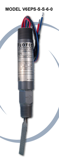
| V6EPS-S-S-6-0
|
Stainless Steel
|
No Tee
|
None
|
| V6EPB-B-S-LF
|
Brass
|
1/2"
|
Low Flow Model, Brass
|
| V6EPS-S-S-LF
|
Stainless Steel
|
1/2"
|
Low Flow Model, Stainless Steel
|
|
|
|
|
|
| |
| How to Configure a Model:
|
| Example
|
V6
|
B
|
EP
|
B
|
S
|
2
|
B
|
MT
|
V6EPB-B-S-2-B-MT flow switch; brass upper housing, brass lower housing, brass tee with 3/4" NPT connections, SPDT snap switch, and high temperature option
|
| Series
|
V6
|
|
|
|
|
|
|
|
Series V6 flow switch
|
| Construction
|
|
EP
|
|
|
|
|
|
|
Explosion proof
|
| Upper Body
|
|
|
B
S
|
|
|
|
|
|
Brass
Stainless Steel
|
| Lower Body
|
|
|
|
B
S
|
|
|
|
|
Brass
Stainless Steel
|
| Circuit (Switch)
|
|
|
|
|
S
D
|
|
|
|
SPDT
DPDT
|
| Tee Connection Size
|
|
|
|
|
|
1
2
3
4
5
6
LF
|
|
|
1/2" NPT
3/4" NPT
1" NPT
1-1/4" NPT
1-1/2" NPT
2" NPT
Low Flow Model (1/2" NPT connections)
|
| Tee Material
|
|
|
|
|
|
|
MI
FS
B
S
0
|
|
Iron
Forged Steel
Brass
Stainless Steel
No tee, field trimmable vane
(For LF Model no tee material chosen, tee material matches lower housing choice)
|
| Options
|
|
|
|
|
|
|
|
CSA
AT
MV
MT
VIT
|
CSA approved construction (includes JCT option standard)
ATEX approved construction with junction box
Gold contacts on snap switch for dry circuits (see specifications for ratings)
High temperature option rated 400°F (205°C) (see specifications for ratings)
Viton® O-rings in place of Buna-N on low flow models
|
|
|
|
| |
| Approximate Actuation - Deactuation Flow Rates
|
| APPROXIMATE ACTUATION-DEACTUATION
|
| FLOW RATES FOR AIR
|
| Upper figures are SCFM, Lower figures in LPM
|
| Pipe Size
|
Actuate
|
Deactuate
|
| 1/2" |
6.50
180 |
5.00
120 |
| 3/4" |
10.0
300 |
8.00
240 |
| 1" |
14.0
420 |
12.0
360 |
| 1-1/4" |
21.0
600 |
18.0
540 |
| 1-1/2" |
33.0
960 |
30.0
840 |
| 2" |
43.0
1200 |
36.0
1020 |
|
|
|
| APPROXIMATE ACTUATION-DEACTUATION
|
| FLOW RATES FOR COLD WATER
|
| Upper figures are GPM, Lower figures in LPM
|
| Pipe Size
|
Actuate
|
Deactuate
|
| 1/2" |
1.50
5.667 |
1.00
3.83 |
| 3/4" |
2.00
7.5 |
1.25
4.67 |
| 1" |
3.00
11.33 |
1.75
6.67 |
| 1-1/4" |
4.00
15.17 |
3.00
11.3 |
| 1-1/2" |
6.00
22.67 |
5.00
19 |
| 2" |
10.00
37.83 |
8.50
32.2 |
|
|
|
|
| |
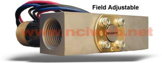
| Model V6 Low Flow Version - Field Adjustable Actuation Point - Rated for 1450 psig Max Pressure
|
| The Low Flow V6, like the standard model, features a leak-proof solid brass low housing and magnetically actuated snap
switch. The machined tee is available in brass or stainless steel with all wetted parts of like materials and Buna-N
or optional Viton O-Rings. The actuating mechanism is a plunger opposing a spring with an adjustable bypass valve
to set the actuation rate. Piping connections are 1/2" female NPT for in-line mounting. Units are explosion-proof
and rated to 1450 psig (100 bar). UL, CSA and ATEX listings match standard V6. Weight is 1-1/2 lbs. |
| |
| V6 LOW FLOW MIN-MAX FLOW RATES IN 1/2" PIPE
|
| MEDIA
|
ACTUATE
|
DEACTUATE
|
| GPM-Water |
.04-0.75 |
.03-0.60 |
| M³HR-Water |
.01-0.17 |
.007-.136 |
| SCFM-Air |
.18-2.70 |
.15-2.0 |
| NM³S-Air |
.0001-.0013 |
.0001-.001 |
|
|
|
|
|
| |
| Previous Page
|
|
|
|